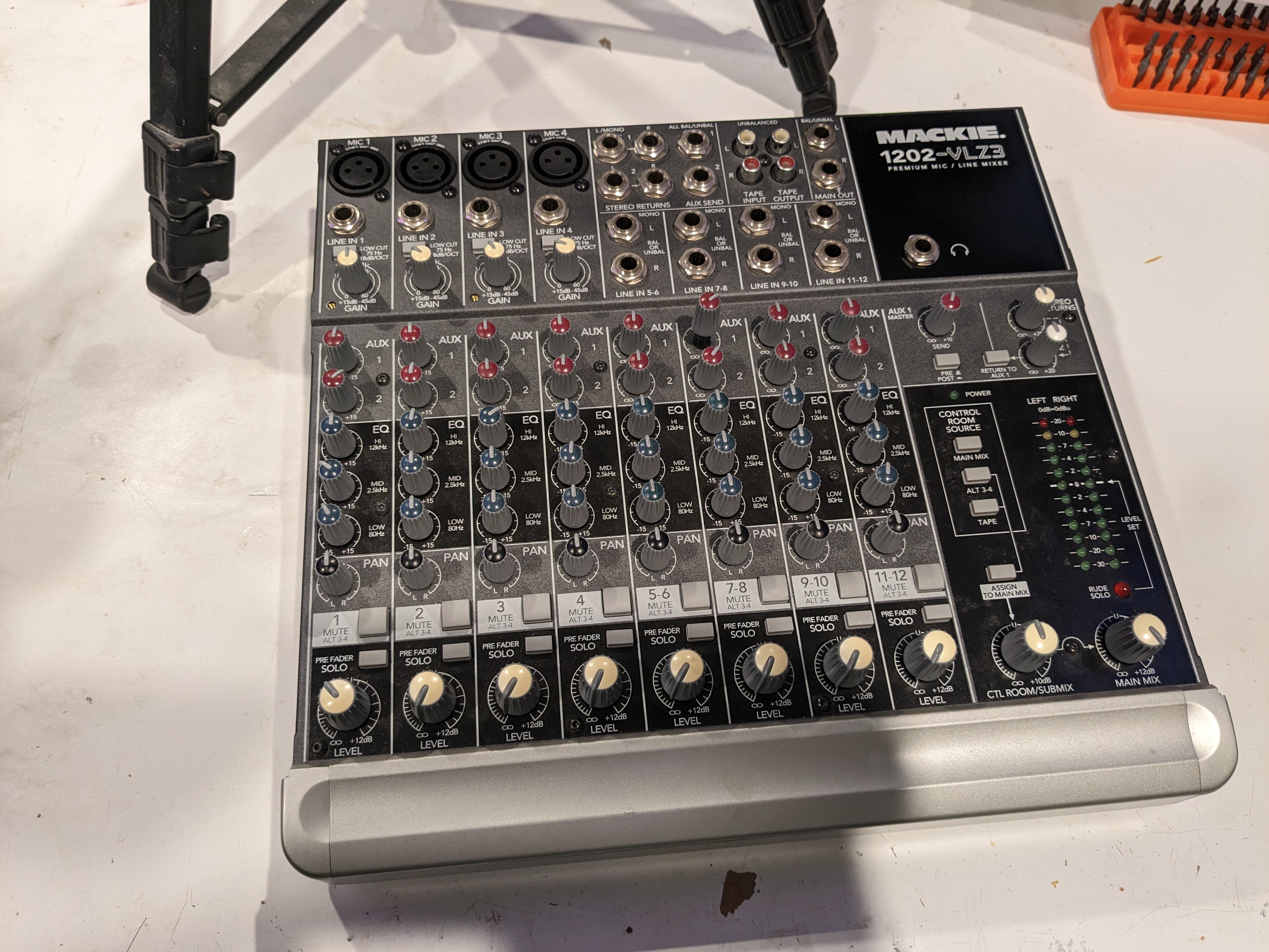
Repairing a Mackie 1202-VLZ3 Mixing Desk (no power on)
Video: youtube
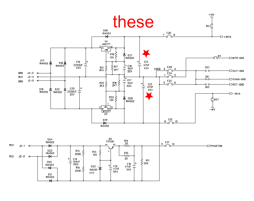
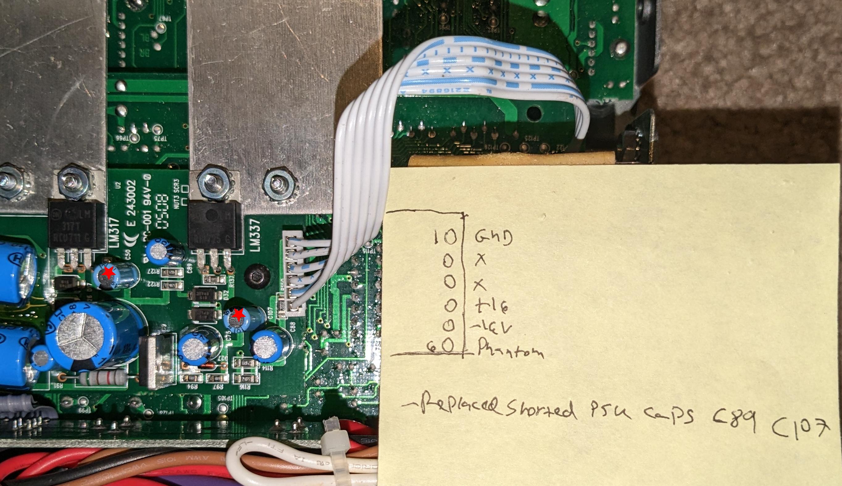
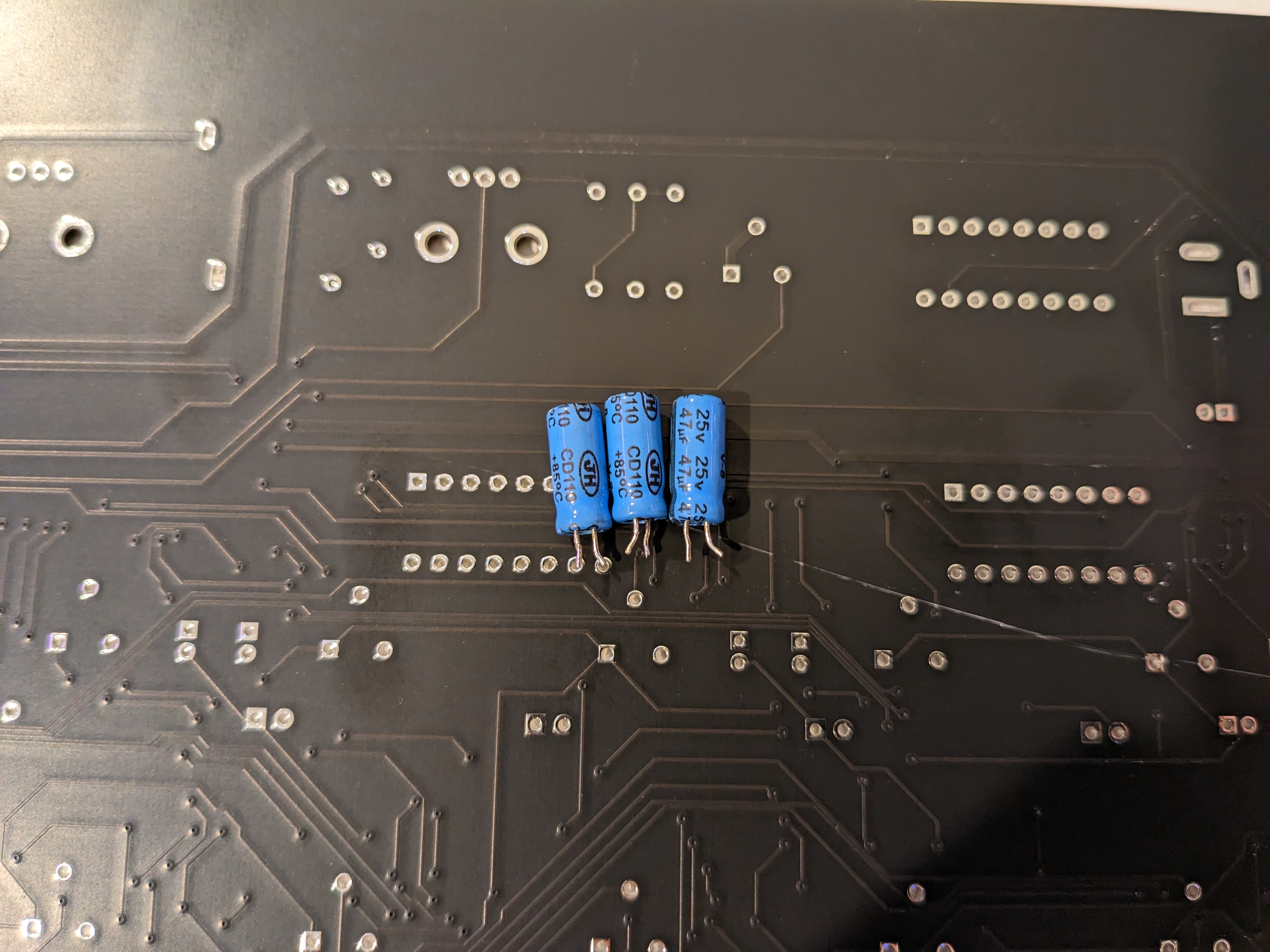
I came across a Mackie 1202-VLZ3 at the recycler's. It would not power on. The primary symptom was no power LED activity, and a hot electronics smell. After some debugging, it turned out that two 47uF 25V electrolytic capacitors in the power supply were shorted internally (C89, C107), as well as one more capacitor of the same type in the VU meter +16V supply circuit. I determined this by measuring the voltage rails with a multimeter. The pinout is shown in the attached images, or down from the heatsink side of the board: GND, X, X, +16V, -16V, Phantom Power.
I failed to find the service manual, but did get one for the similar 1202-VLZ. The general layout is very similar. I only noticed minor component substitutions. The component designators are completely different.
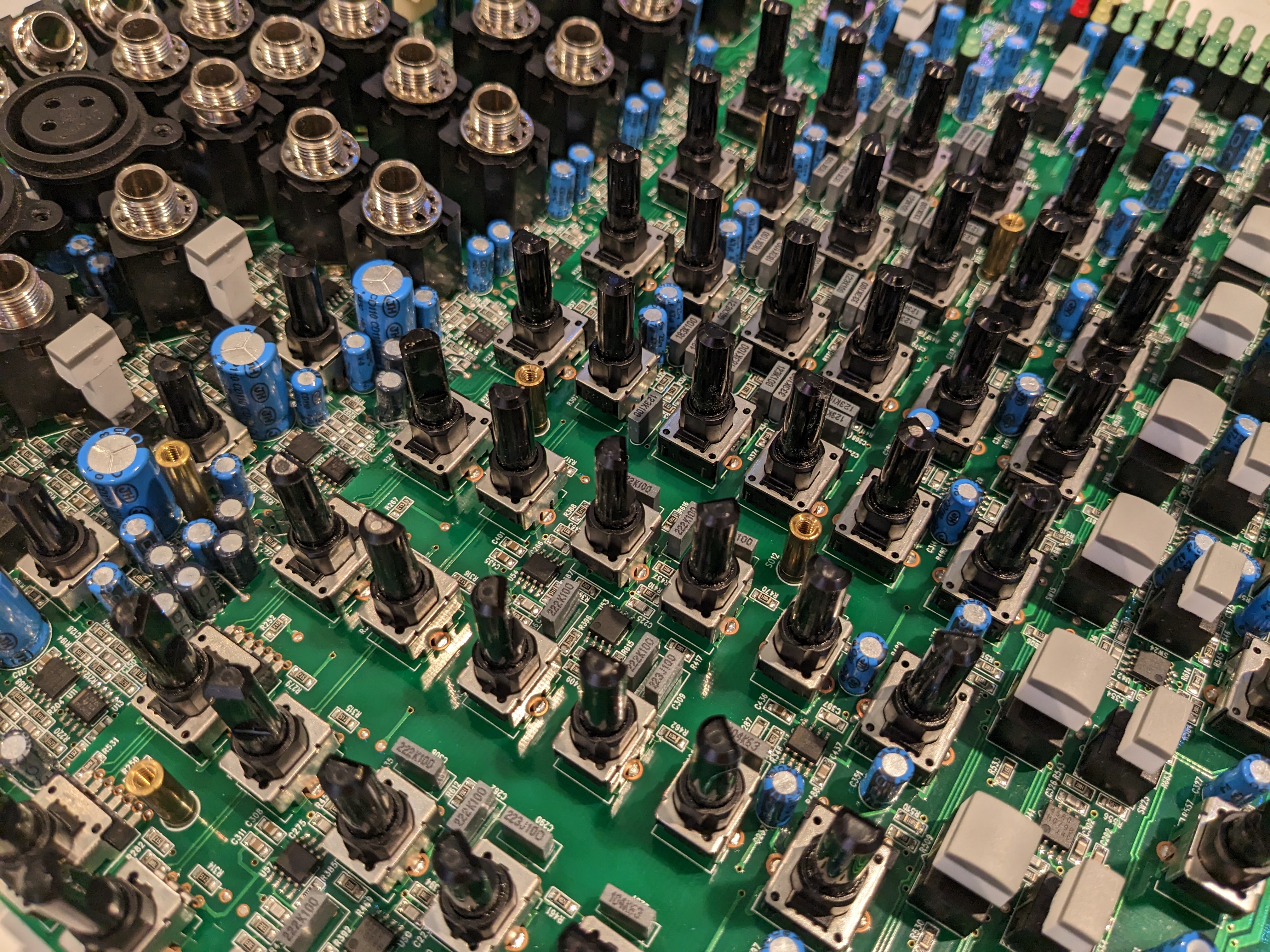
There are over 100 capacitors of similar type in the device. I just identified and replaced the failed ones. If you will be using a similar unit in a high-stakes application such as live events, consider replacing all of them. Regarding identifying the failed capacitors, I have no advice other than to invest in a multimeter that can measure milliohms and measure across all capacitors, replacing the lowest-resistance one and re-measuring repeatedly until the fault clears. None of the capacitors should have less than a kiloohm across it.
To gain access to the circuit boards, it will be necessary to undo all the jack socket nuts, pull off all the knobs (I used two of this printable crowbar in tandem to avoid breaking the stem or marring the device), remove the screws holding on the XLR and RCA jacks, remove all the socket cap screws on the face of the unit, and remove the screws on the sides, front, and rear of the device. The screws holding in the power socket and voltage selector can remain. The jack socket nuts are 1/2", consider using this non-marring finger drive wrench.
Be very gentle with the flimsy bare wire links joining the two signal boards, they are extremely fragile. Four failed during my work (confounding my diagnosis!) and had to be re-attached. I also ripped out a pad's through-plating because I let my impatience get the better of me :X
The service manual is attached here - again, it is for another similar unit. I found it here originally.
Good luck!