Salvaged Battery Pack Optimizer

tl;dr A tool to design better battery packs by dividing cells into groups of similar capacity (mAh). Uses iterative maximum weight maximum cardinality matching to create optimal groups of 2S, 4S, 8S, or 16S configurations.
» Read full post.Haltech DTC Trouble Codes as CSV
For my supercharged Alfa Spider's custom dash firmware, I need to translate DTC codes to text programmatically. Haltech only provides a list in graphical tables. I converted this to CSV.
» Read full post.1974 Alfa Romeo Spider Dash 3D Scans
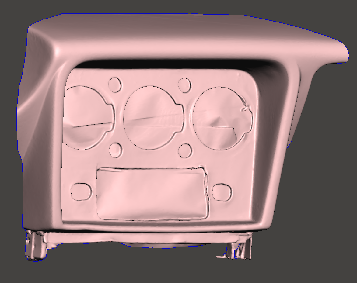
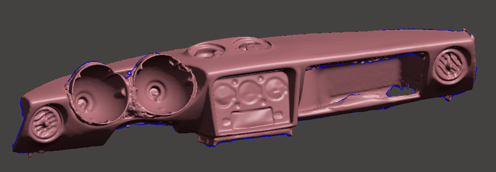
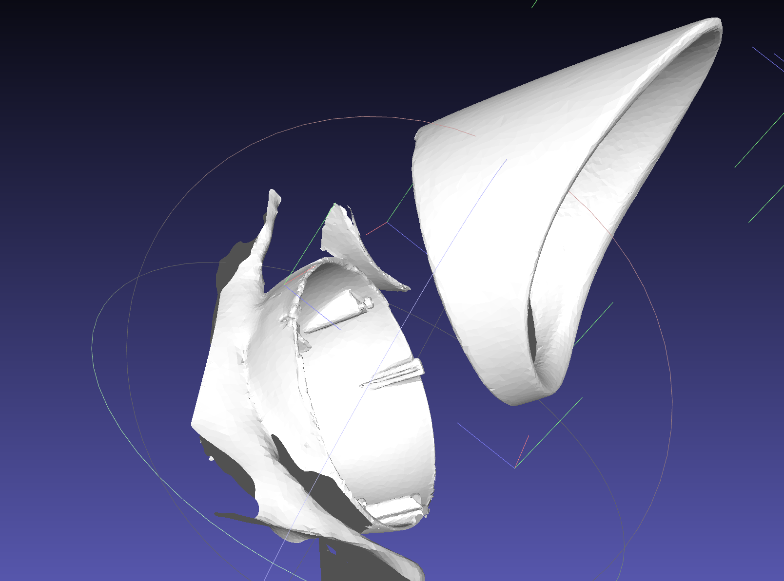
Doing some major interior remodeling and took the scanner to my 115 (spica). I'm completely replacing the instrumentation (long story, major changes have been made to my car). Figured someone may want the files. They're a little bit rough on the edges because my Creality CR-Scan Otter isn't the most powerful scanner, but the main center gauge section is accurate. There's a separate low-resolution overall scan, too.
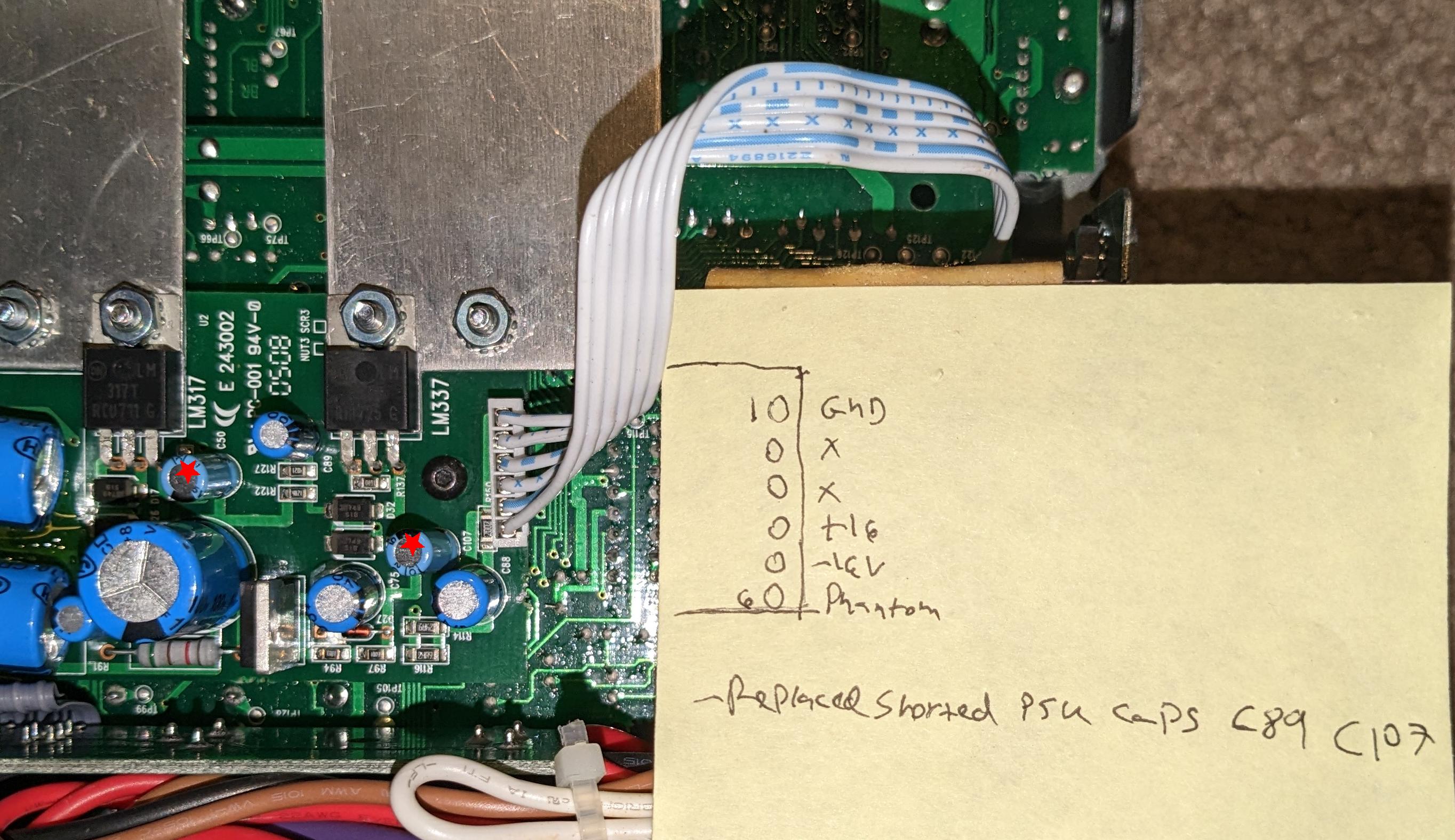
» Read full post.Panasonic KX-W50TH KX-W60TH Thermal Typewriter Service Manual
Mirror for my scanned copy of the Panasonic KX-W50TH and KX-W60TH Thermal Typewriter service manual. Scanned by me (with a friend's equipment and guidance, thanks!). Also available on archive.org. Includes full schematics and PCB foil layouts, along with mechanical and electrical theory of operation. A print head calibration procedure is also provided. A good read even if you do not own such a device - plenty of practical circuits to learn from.
» Read full post.Lanterna Superpila LED + Lithium Mod
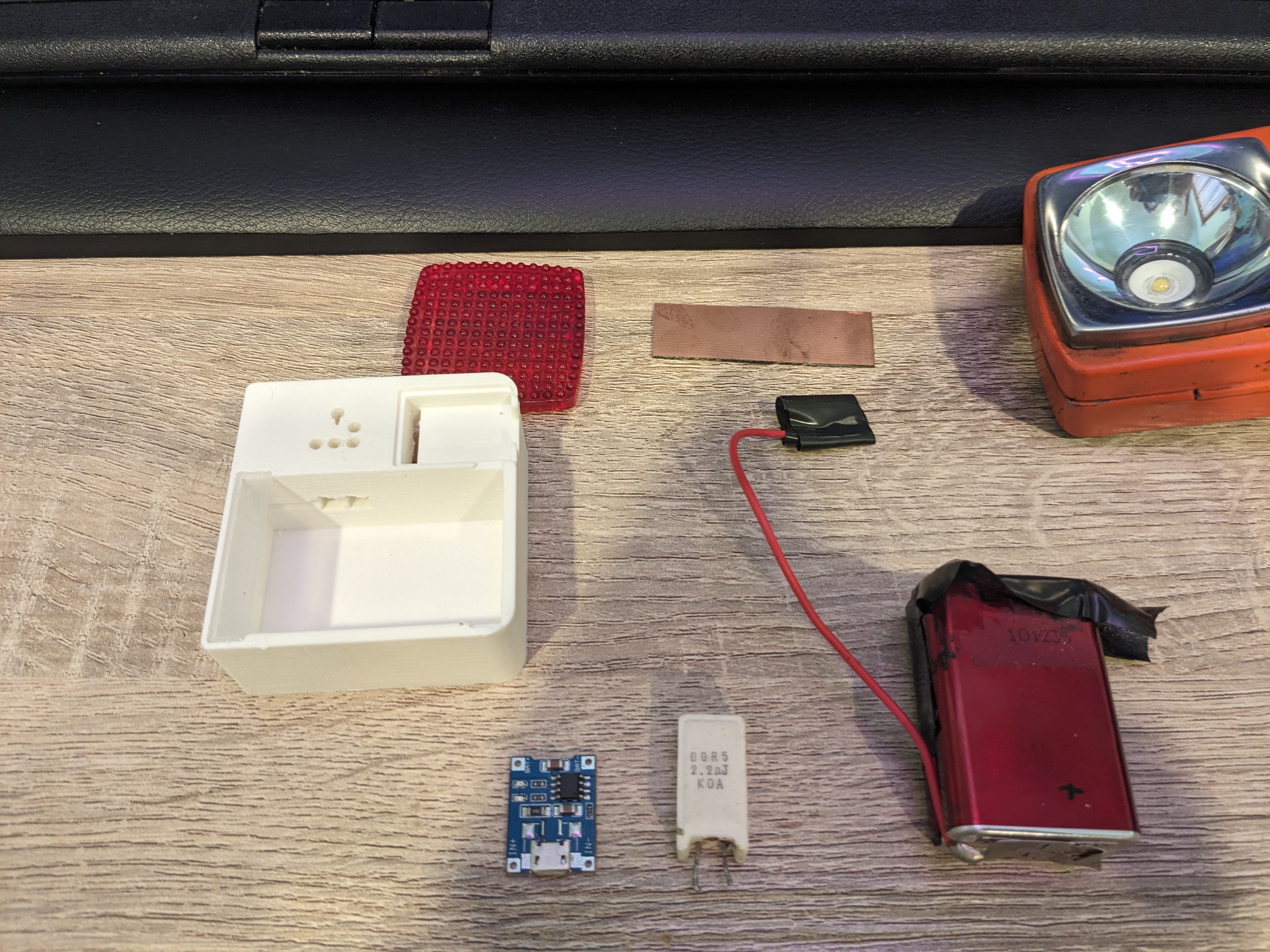
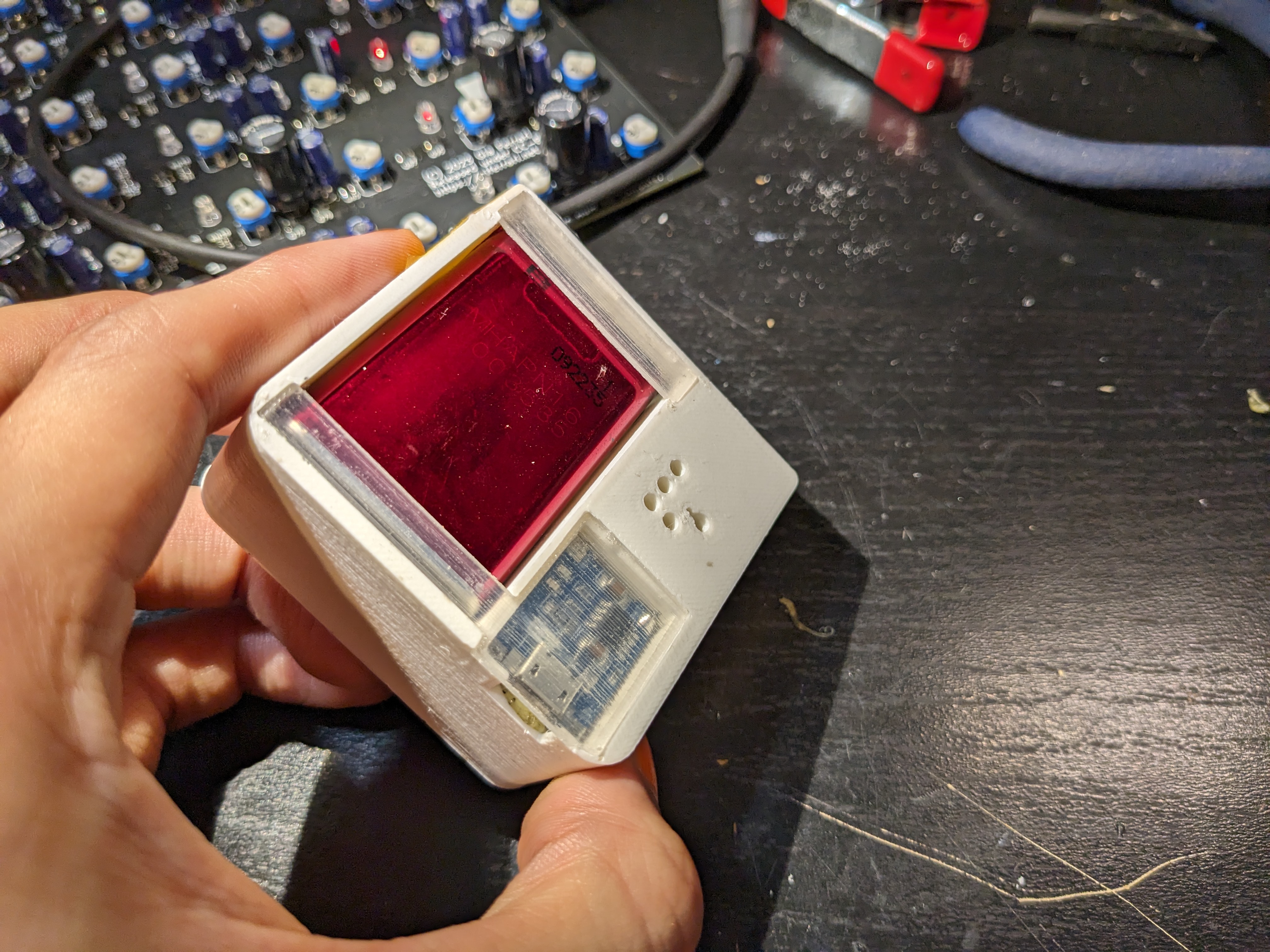
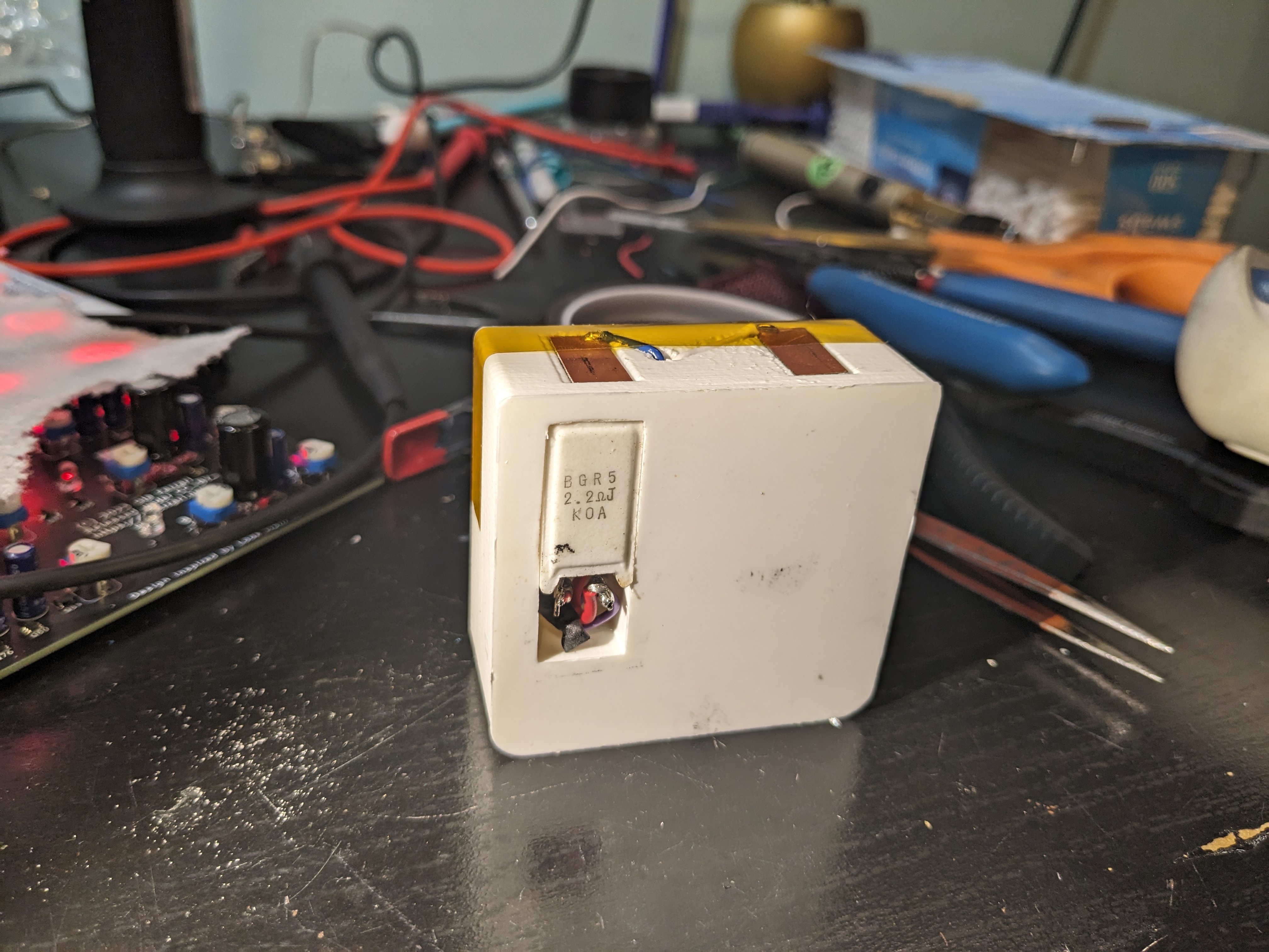
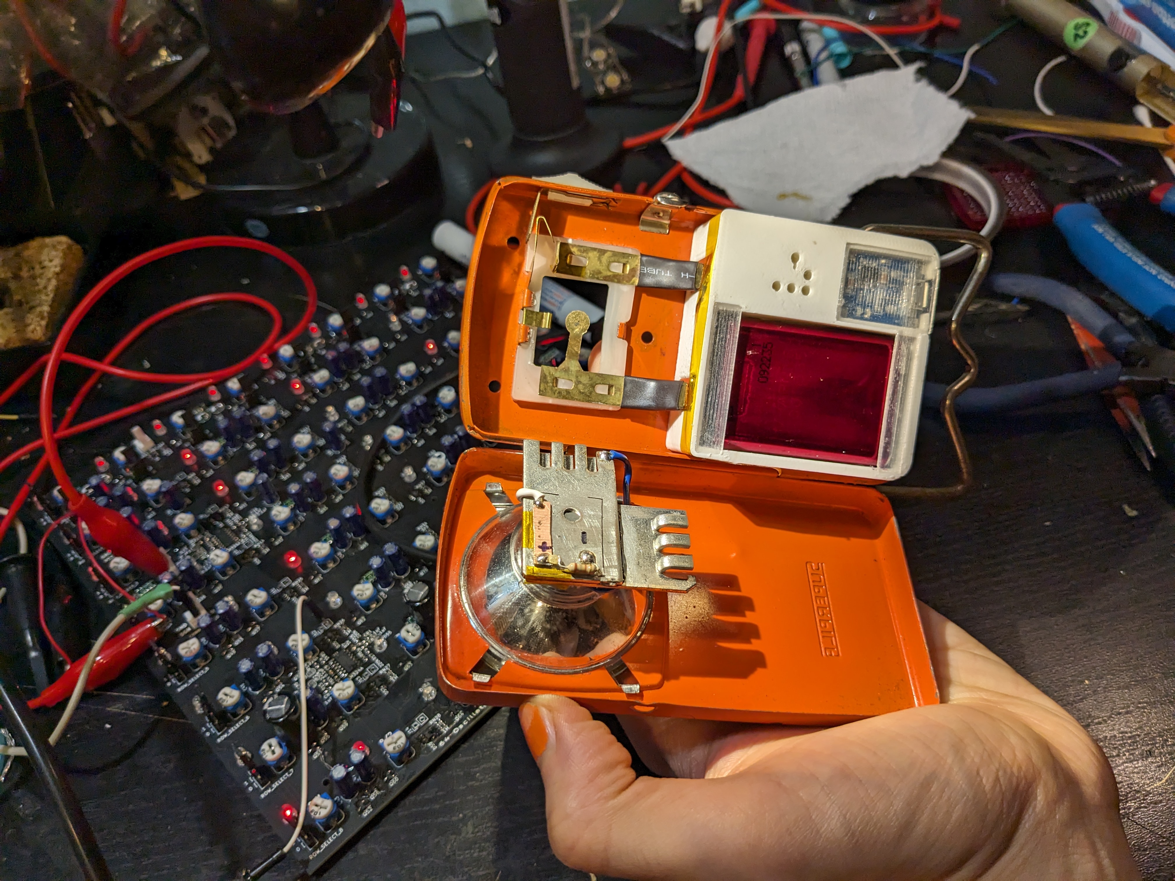
Every object in our lives has a story, and if the observer looks hard enough, they offer a snapshot into a past life, of the long and unlikely path each of us leads. Even something as humble as this Lanterna Superpila I rescued from my great uncle's farm, in a tiny town composed of a half-dozen homes just south of Codroipo, Italy. The specifics of the significance of this particular object are mundane and uninteresting, except to underscore that meaning and connection can be found in the mundane and uninteresting. Seek these connections. Explore them. The world is never boring to the curious - we are surrounded by wonders. Some people take up painting a scene, to more intimately understand a space or event. Others, seeking a similar understanding, write poetry, or compose music. I tend to seek connection via tactile objects. In restoring them, disassembling them, reassembling them, modifying them, we visit the original designers in their space, and we visit their owners in their time and space. By adding our own contributions to the object, we join that chain of events. It is very grounding to me. Even if it's the Engineer's Anthropic Principle: If you look hard enough at a designed object, you can be sure that some poor engineer, somewhere, was frustrated that this particular piece wasn't working right.
» Read full post.
3D Printing LIDAR Survey Topography (GeoTIFF to hollowed resin print)

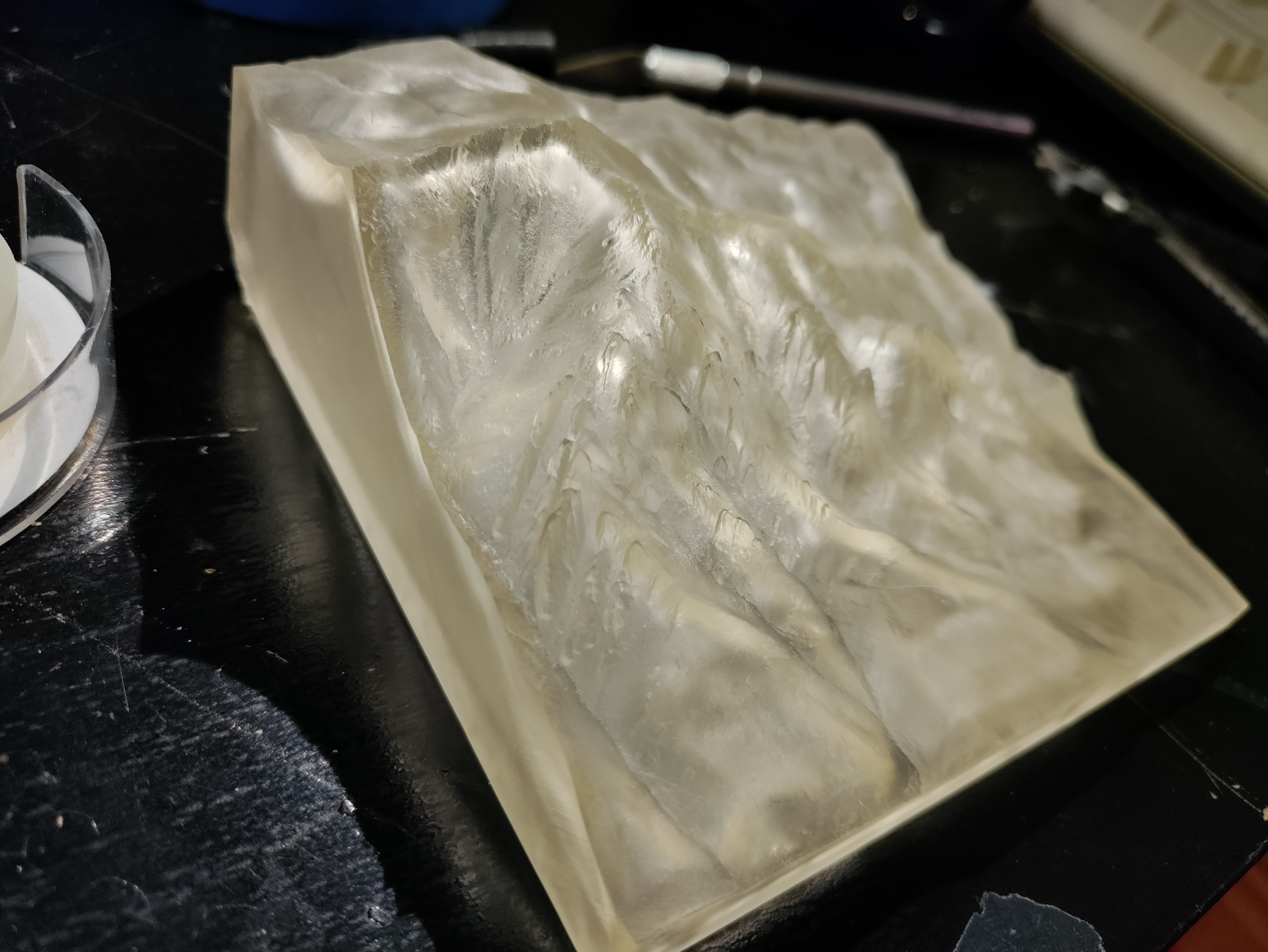
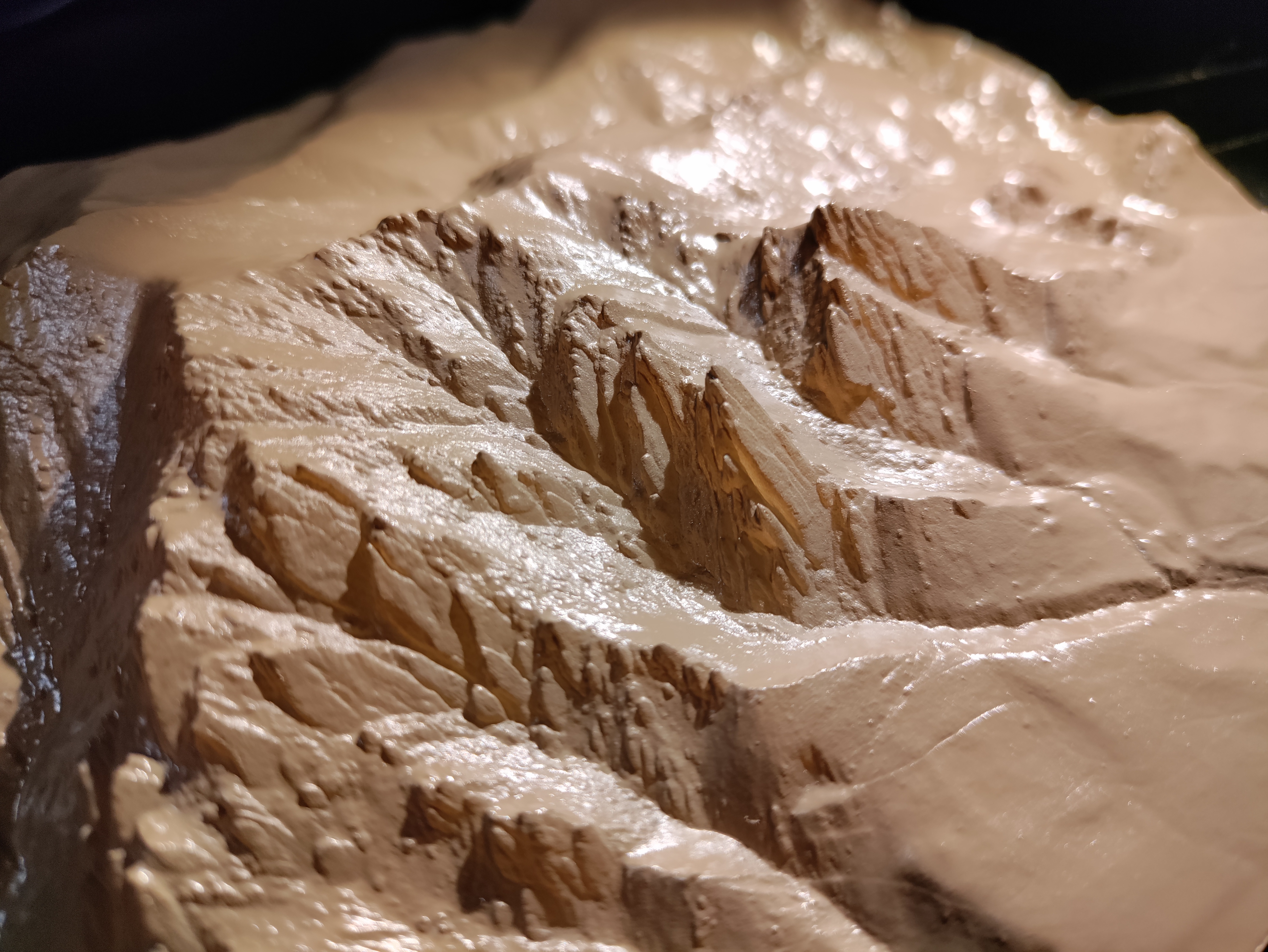
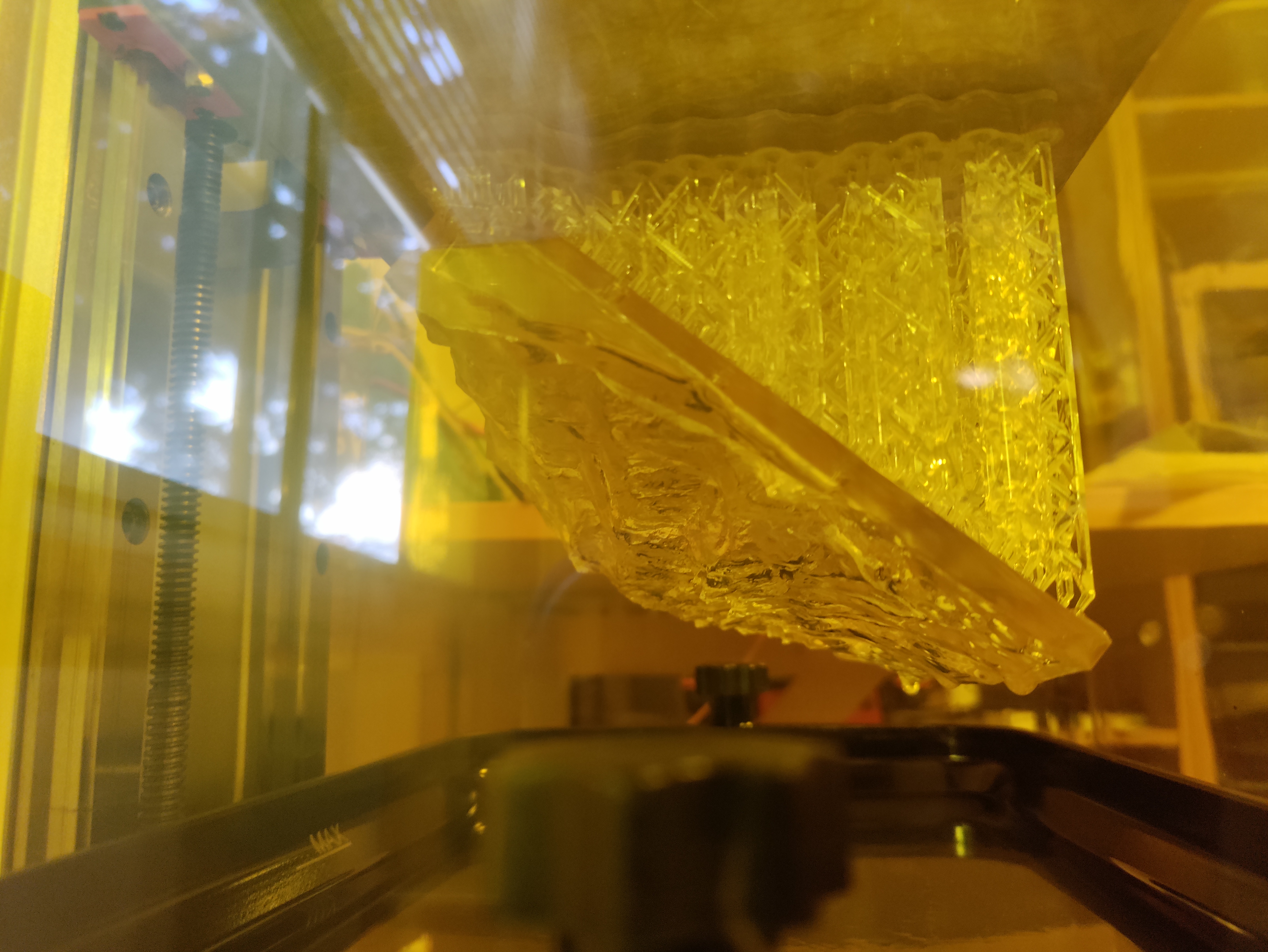
Primary Goals
» Read full post.Software for Toshiba Libretto 50CT (Win95)
I got a request from a YouTuber for the Libretto 50CT's software. Here it is, zipped up on the 50CT itself. 12MB of archives never felt so big 🙂
» Read full post.Stupid simple interrupt-driver IR remote decoder for ATtiny/ATmega
Quick one. For a project, I needed a really simple IR decoder program for an ATtiny85 that (a) Used interrupts for pulse processing, but (b) didn't use a timer interrupt, and (c) worked with an apple remote I had laying around. None of the libraries I found did this (mostly b, plus none really had the 85 in mind), so I whipped up my own. It's stupid. It's simple. It works well enough for me. Just whack your IR decoder's output to the 85's physical pin 3, hook a 9600,8,n,1 uart input to physical pin 2, press buttons on your remote, and marvel at the numbers and stuff appearing on your screen. Enough blab, here's the goods. This should work fine with pretty much any AVR, as long as you fix up the interrupt configuration in setup() for your particular chip.
» Read full post.Classic Mac -> PS2 mouse adapter
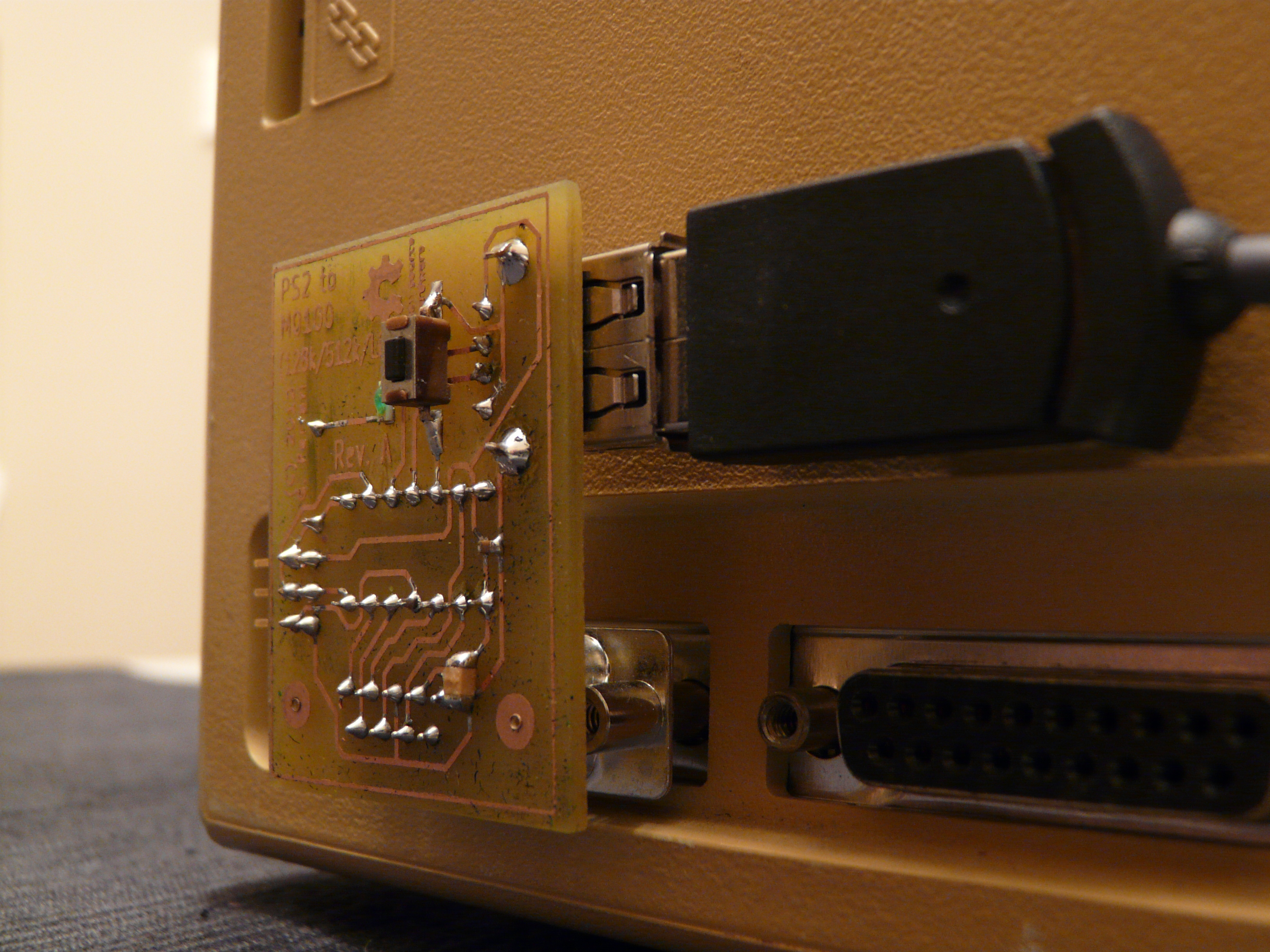
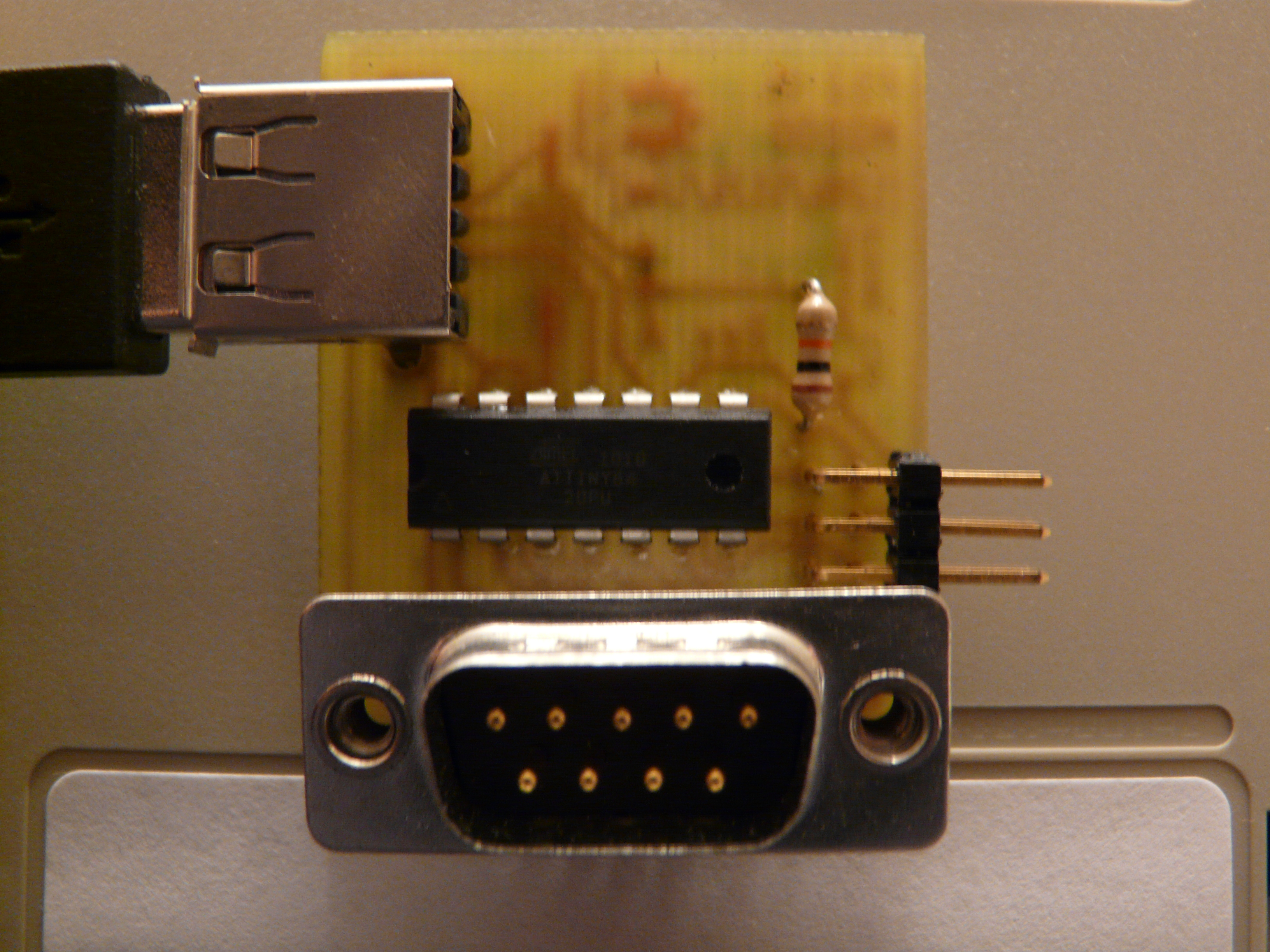
So I made a little adapter so I can connect PS/2 mice to the pre-ADB Classic Macs (128k, 512k, 512ke, probably Lisa). They use a really simple scheme: two pairs of quadrature inputs (one for X, one for Y), and one input for the single button. 5v is provided for the mouse. Perfect for a little microcontroller like the ATtiny to interface to (which is funny, because the ATtiny is capable of a far faster clock speed than the Macs...).
» Read full post.